CoffeeBot4180
CoffeeBot
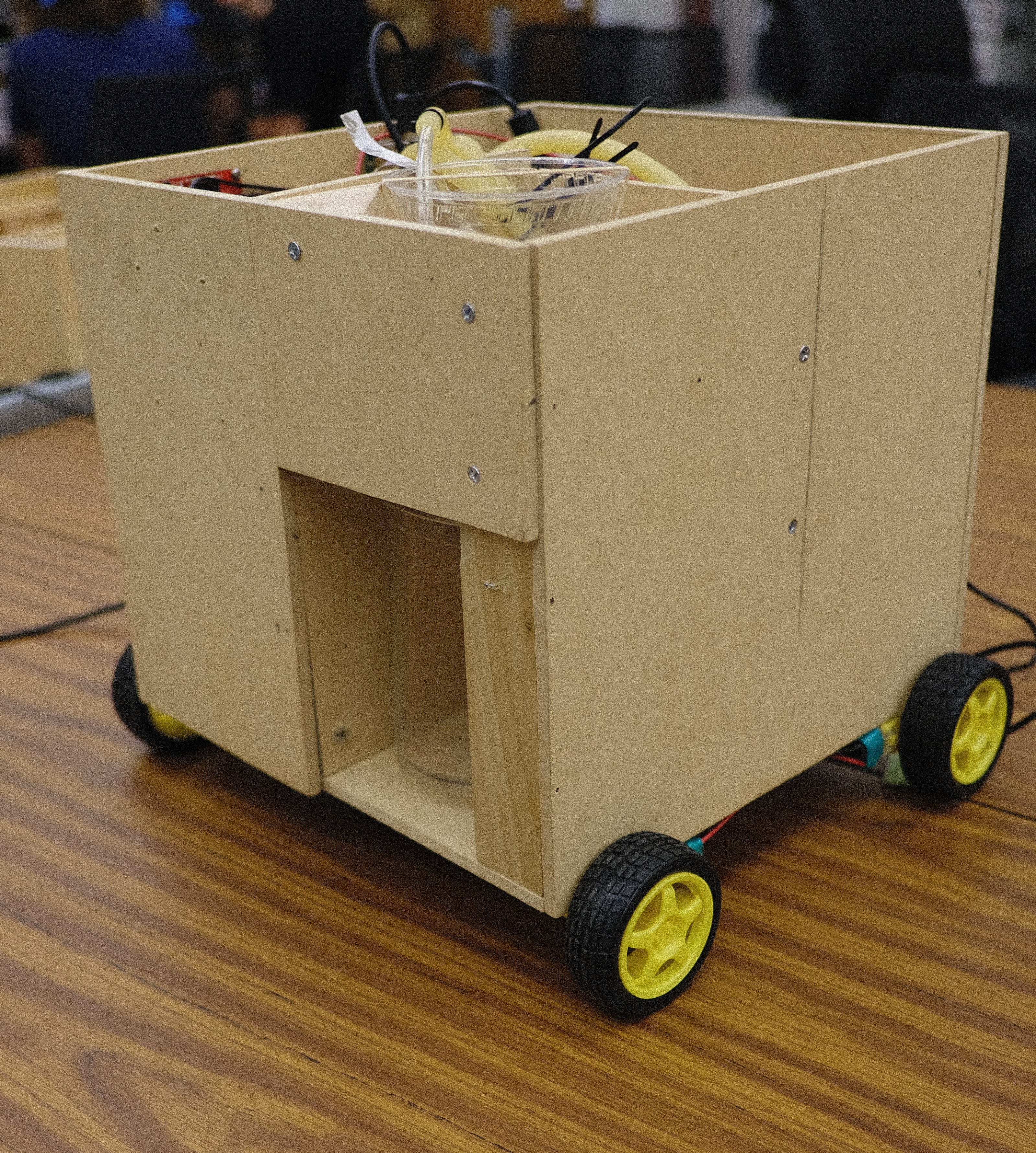
Table of Contents
Overview
Parts List
System Architecture
Physical Enclosure
Schematics
Wiring Guide
GUI
Backend
Results
Improvements
Overview
The intent behind this project is to prepare high quality cold brew coffee with accurate measurements with a click of a button. Hence, CoffeeBot is designed for users to customize their coffee drinks using remote assistance to save time and effort. The bot is portable and includes delivery options with interactive lighting.
Parts List:
1 x mBed LPC1768 microcontroller
1 x Raspberry Pi Model 3 B
1 x 8-channel Relay board
4 x Peristaltic pumps
1 x RGB LED Strip
1 x DC 12V Motor Driver
1 x Toy DC Motor Set
System Architecture
The Architecture is divided into two sections: Motor Control and Pumping. Raspberry Pi handles the pumping while the mBed controls the Motor Driver. Raspberry Pi interfaces with the mBed serially via USB cable. A 12V/5A Power Supply supplies power to the motor dirver, perastaltic pumps, and LED strip.
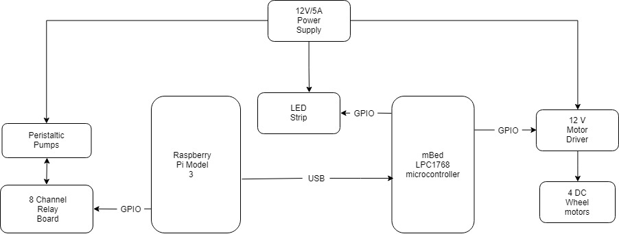
Motor Control
The mBed sends encoded signals to the Motor Driver to control the speed and direction of the motors. Since the driver is only dual channel and there are four motors, the front and back motor of each side are connected in series to both channels.
Pumping
8-channel relay board controls the pump motors by completing the circuit with the power supply. Since there are only 4 pumps, only 4 relay connections are needed abut they can be extendable to control 8 pumps.
Added Effect
There is an LED strip attached to the mBed which acts as an indicator for pumping status. The color changes to Red when the pumps are in Idle mode and switched to Green if the pumps are active.
Physical Enclosure
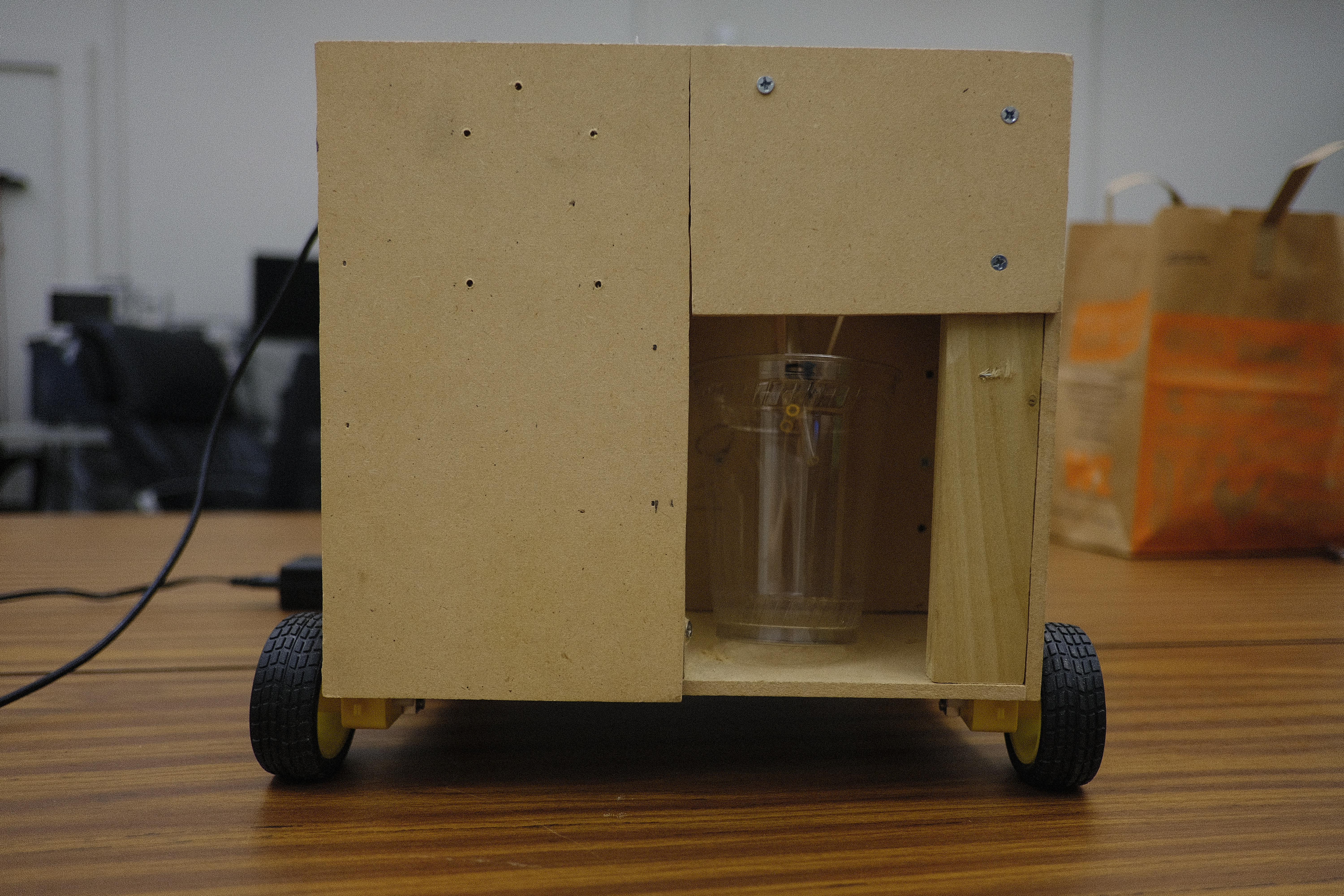
The enclosure is made from MDF board. The enclosure composes of electrical control section (left panel) where the PCBs and circuit elements are mounted, dedicated liquid storage (top right section) for storing liquified sugar, creamer, and flavors, and coffee pumping station (front right section) where the coffee and other liquids are flowing into a cup. The peristaltic pumps, mounted on the bottom panel as displayed in the image, are attached to surgical tubing routed from liquid containers to coffee cup. A funnel mount is placed above the coffee cup for filteration. Wodden support beams are placed along the edges for durabiltiy.
For in-depth list of dimensions, please click here
Schematics
Full Schematic
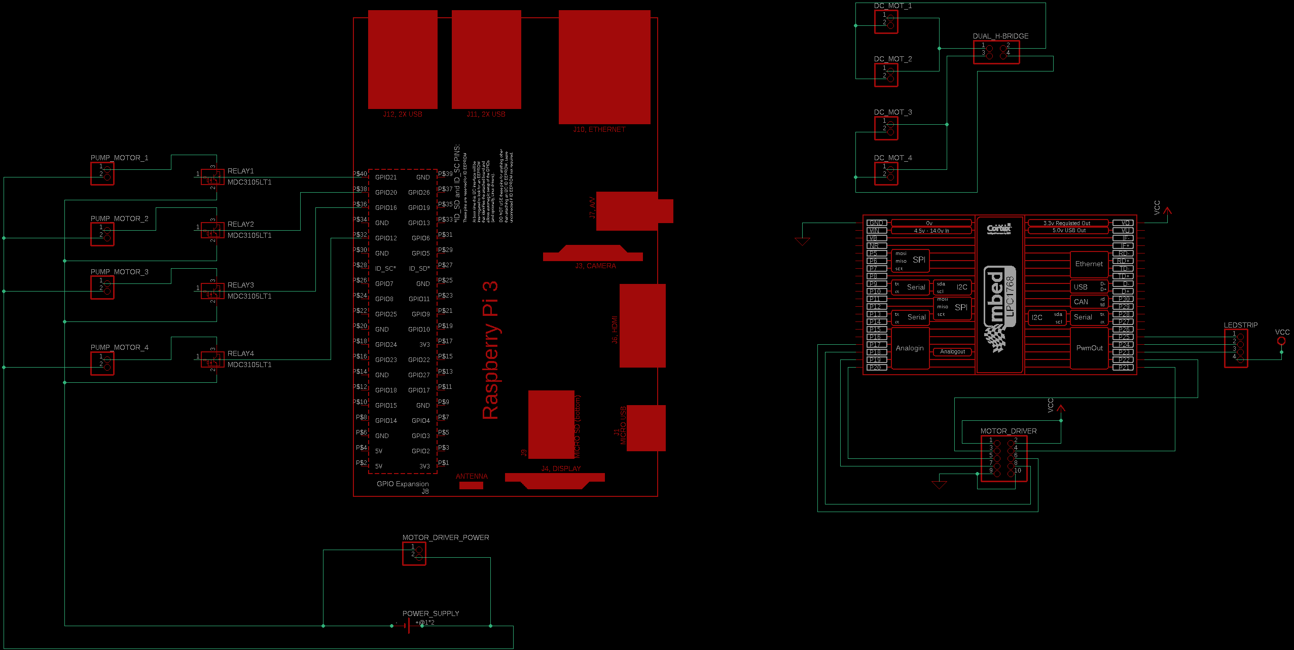
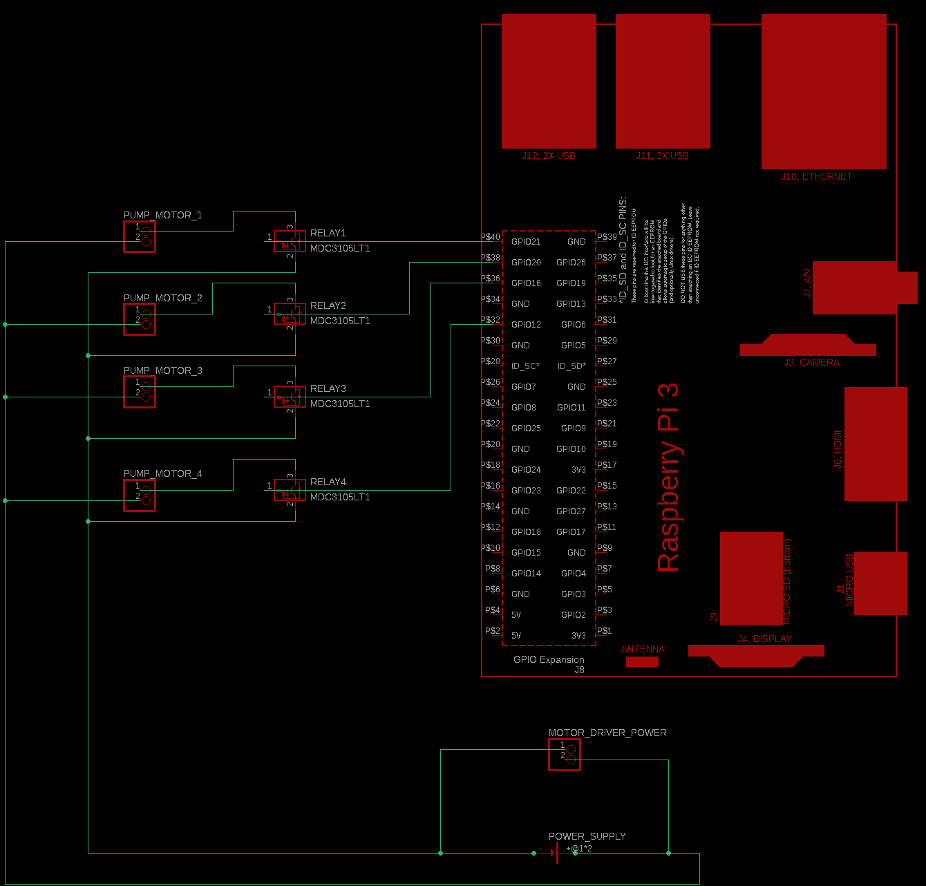
Raspberry Pi Schematic
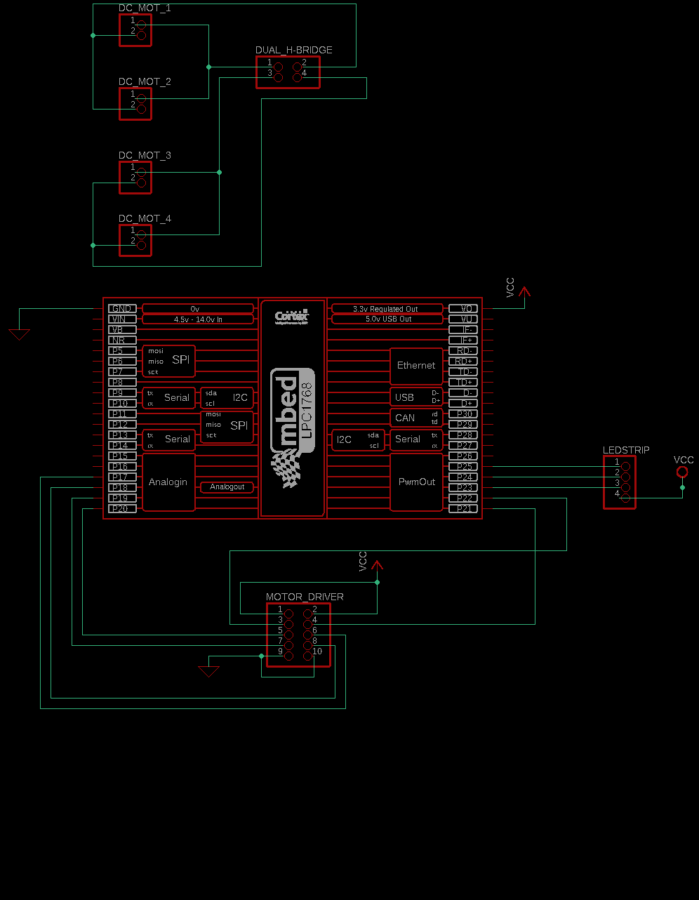
mBed Schematic
Wiring Guide
Raspberry Pi Setup
The pinout for Raspberry Pi Model 3 can be found here
| Raspberry Pi | Relay Board |
|---|---|
| +5V | VCC |
| GPIO 16 | IN 1 |
| GPIO 20 | IN 2 |
| GPIO 21 | IN 3 |
| GPIO 12 | IN 4 |
| GND | GND |
Mbed Setup
The pinout for mBed can be found here
| mBed | Motor Driver |
|---|---|
| VOut | +5V |
| p25 | ENA 1 |
| p26 | ENA 2 |
| p19 | IN 1 |
| p20 | IN 2 |
| p21 | IN 3 |
| p22 | IN 4 |
| GND | GND |
Power Supply Pinout
| Power Supply | Connection |
|---|---|
| +12V | Motor Driver Vin Relay Switches |
| GND | Motor Driver GND Peristaltic Pumps GND |
GUI
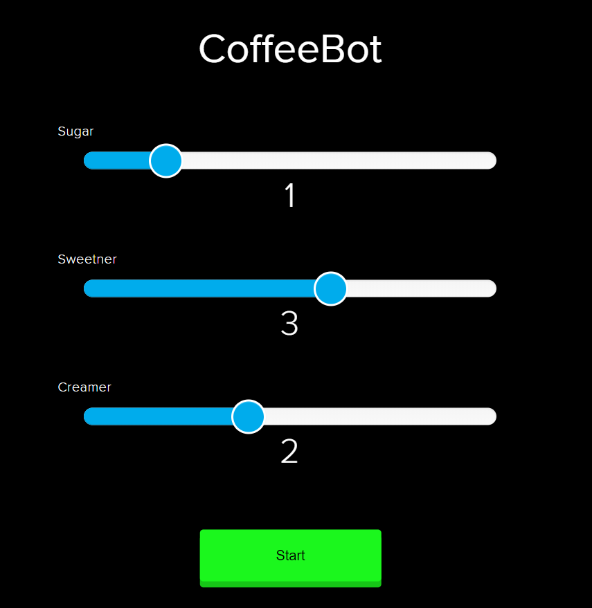
The GUI’s are created using Adafruit IO Dashboards. There are two GUI’s utilized for this project: CoffeeBot and Motor Control.
CoffeBot GUI
Motor Control GUI
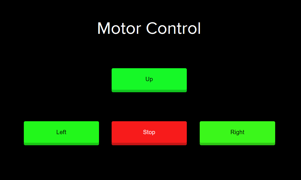
The frontend for the GUI is manually designed by placing sliders, buttons, and text. Each element of the GUI is linked to a feed which is useful when writing a backend program using Python3 on Raspberry Pi. In our case, each pushbutton (CoffeeBot uses Start, Motor Control uses Up, Stop, Left, Right) sends a 1 or 0 to indicate that the user has pressed the button. For sliders (Sugar, Creamer, and Sweetner), a value between 0 and 5 is sent to the backend Python3 program. Since each element is utilized by its own feed, there is no interference between the values.
Caution: The Adafruit IO free subscription is only limited to 30 feeds per minute which means there should be a time delay of 1 sec to cycle between the feeds. Also, there are limited number of feeds and dashboards that the user can create. To ensure faster and more responsive update rate, the user can pay $9.99 subscription fee which extends the feed update rate to 60 feeds/min and unlimited dashboards and feeds.
For an in-depth Adafruit IO tutorial, Please click here
Raspberry Pi Backend
Raspberry Pi recieves the values that are sent from the GUI to initiate the functionality process. There are three programs written on Raspberry Pi: CoffeeBot.py (Python), MotorControl.py (Python), RaspiToMbed.cc (C++).
CoffeeBot.py: The values that are received from the CoffeBot GUI are used here. The slider values control the flow rate of the liquid by tablespoon increments by turning on the relay switch. For example: 2 tablespoons of sugar turns the relay switch for 2 x one table spoon time seconds. The one table spoon time can vary between different pumps and variable voltages which can be measured and set to the appropriate time. Also, the LED strip value of 1 is passed to RaspiToMbed.cc program when the pumps are active.
MotorControl.py: The program receives the input from Motor Control GUI and passes a value between 0 and 4 to RaspiToMbed.cc.
| GUI Command | Value passed to Mbed |
|---|---|
| No button pressed | 0 |
| Up | 1 |
| Stop | 2 |
| Left | 3 |
| Right | 4 |
RaspiToMbed.cc: The values(LED Strip and Motor Control) that are updated in the python programs are passed to mBed serially.
Raspberry Pi files are available here
mBed Backend
There is only one program written in mBed named CoffeeBot.cc which uses RTOS to run threads to control the motors and LED. Serial library is used to recieve the commands from Raspberry Pi.
mBed files are available here
Results

Improvements
- Having a battery that supplies enough power to run the motors and pumps
- More peristaltic pumps to add flavors and custom drinks
- Create one GUI that can support Motor Control and Pumping and add some custom drinks pushbutton
- Better Motors and reliable tires